

Replace a DIMM - AFF A300
 Suggest changes
You must replace a DIMM in the controller when your storage system encounters errors such as, excessive CECC (Correctable Error Correction Codes) errors that are based on Health Monitor alerts or uncorrectable ECC errors, typically caused by a single DIMM failure preventing the storage system from booting ONTAP.
All other components in the system must be functioning properly; if not, you must contact technical support.
You must replace the failed component with a replacement FRU component you received from your provider.
Step 1: Shut down the impaired controller
Shut down or take over the impaired controller using the appropriate procedure for your configuration.
Take over and halt the impaired controller so that the healthy controller continues to serve data from the impaired controller's storage. To do this, you suppress automatic case creation in AutoSupport, disable automatic giveback, and bring the impaired controller to the LOADER prompt. The LOADER prompt is the safe halted state from which you can replace the FRU.
-
If you have a SAN system, you must have checked event messages (
cluster kernel-service show) for the impaired controller SCSI blade. Thecluster kernel-service showcommand (from priv advanced mode) displays the node name, quorum status of that node, availability status of that node, and operational status of that node.Each SCSI-blade process should be in quorum with the other nodes in the cluster. Any issues must be resolved before you proceed with the replacement.
-
If you have a cluster with more than two nodes, it must be in quorum. If the cluster is not in quorum or a healthy controller shows false for eligibility and health, you must correct the issue before shutting down the impaired controller; see Synchronize a node with the cluster.
-
If AutoSupport is enabled, suppress automatic case creation by invoking an AutoSupport message:
system node autosupport invoke -node * -type all -message MAINT=<number of hours down>hThis prevents automatic support cases from being opened during your planned maintenance window. The maximum suppression duration is 72 hours. If your maintenance completes early, you can re-enable case creation by invoking an AutoSupport message with
MAINT=END. For more information, see How to suppress automatic case creation during scheduled maintenance windows.The following AutoSupport message suppresses automatic case creation for two hours:
cluster1:> system node autosupport invoke -node * -type all -message MAINT=2h -
Disable automatic giveback:
-
Enter the following command from the console of the healthy controller:
storage failover modify -node impaired_node_name -auto-giveback false -
Enter
ywhen you see the prompt Do you want to disable auto-giveback?
-
-
Take the impaired controller to the LOADER prompt:
If the impaired controller is displaying… Then… The LOADER prompt
Go to the next step.
Waiting for giveback…
Press Ctrl-C, and then respond
ywhen prompted.System prompt or password prompt
Take over or halt the impaired controller from the healthy controller:
storage failover takeover -ofnode impaired_node_name -halt trueThe -halt true parameter brings you to the LOADER prompt.
To shut down the impaired controller, you must determine the status of the controller and, if necessary, switch over the controller so that the healthy controller continues to serve data from the impaired controller storage.
-
You must leave the power supplies turned on at the end of this procedure to provide power to the healthy controller.
-
Check the MetroCluster status to determine whether the impaired controller has automatically switched over to the healthy controller:
metrocluster show -
Depending on whether an automatic switchover has occurred, proceed according to the following table:
If the impaired controller… Then… Has automatically switched over
Proceed to the next step.
Has not automatically switched over
Perform a planned switchover operation from the healthy controller:
metrocluster switchoverHas not automatically switched over, you attempted switchover with the
metrocluster switchovercommand, and the switchover was vetoedReview the veto messages and, if possible, resolve the issue and try again. If you are unable to resolve the issue, contact technical support.
-
Resynchronize the data aggregates by running the
metrocluster heal -phase aggregatescommand from the surviving cluster.controller_A_1::> metrocluster heal -phase aggregates [Job 130] Job succeeded: Heal Aggregates is successful.
If the healing is vetoed, you have the option of reissuing the
metrocluster healcommand with the-override-vetoesparameter. If you use this optional parameter, the system overrides any soft vetoes that prevent the healing operation. -
Verify that the operation has been completed by using the metrocluster operation show command.
controller_A_1::> metrocluster operation show Operation: heal-aggregates State: successful Start Time: 7/25/2016 18:45:55 End Time: 7/25/2016 18:45:56 Errors: - -
Check the state of the aggregates by using the
storage aggregate showcommand.controller_A_1::> storage aggregate show Aggregate Size Available Used% State #Vols Nodes RAID Status --------- -------- --------- ----- ------- ------ ---------------- ------------ ... aggr_b2 227.1GB 227.1GB 0% online 0 mcc1-a2 raid_dp, mirrored, normal...
-
Heal the root aggregates by using the
metrocluster heal -phase root-aggregatescommand.mcc1A::> metrocluster heal -phase root-aggregates [Job 137] Job succeeded: Heal Root Aggregates is successful
If the healing is vetoed, you have the option of reissuing the
metrocluster healcommand with the -override-vetoes parameter. If you use this optional parameter, the system overrides any soft vetoes that prevent the healing operation. -
Verify that the heal operation is complete by using the
metrocluster operation showcommand on the destination cluster:mcc1A::> metrocluster operation show Operation: heal-root-aggregates State: successful Start Time: 7/29/2016 20:54:41 End Time: 7/29/2016 20:54:42 Errors: - -
On the impaired controller module, disconnect the power supplies.
Step 2: Open the controller module
To access components inside the controller, you must first remove the controller module from the system and then remove the cover on the controller module.
-
If you are not already grounded, properly ground yourself.
-
Loosen the hook and loop strap binding the cables to the cable management device, and then unplug the system cables and SFPs (if needed) from the controller module, keeping track of where the cables were connected.
Leave the cables in the cable management device so that when you reinstall the cable management device, the cables are organized.
-
Remove and set aside the cable management devices from the left and right sides of the controller module.
![Removing the cable management arms][](../media/drw_32xx_cbl_mgmt_arm.png)
-
Loosen the thumbscrew on the cam handle on the controller module.
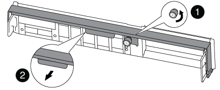

Thumbscrew

Cam handle
-
Pull the cam handle downward and begin to slide the controller module out of the chassis.
Make sure that you support the bottom of the controller module as you slide it out of the chassis.
Step 3: Replace the DIMMs
To replace the DIMMs, locate them inside the controller and follow the specific sequence of steps.
-
If you are not already grounded, properly ground yourself.
-
Check the NVMEM LED on the controller module.
You must perform a clean system shutdown before replacing system components to avoid losing unwritten data in the nonvolatile memory (NVMEM). The LED is located on the back of the controller module. Look for the following icon:

-
If the NVMEM LED is not flashing, there is no content in the NVMEM; you can skip the following steps and proceed to the next task in this procedure.
-
Unplug the battery:

The NVMEM LED blinks while destaging contents to the flash memory when you halt the system. After the destage is complete, the LED turns off. -
If power is lost without a clean shutdown, the NVMEM LED flashes until the destage is complete, and then the LED turns off.
-
If the LED is on and power is on, unwritten data is stored on NVMEM.
This typically occurs during an uncontrolled shutdown after Data ONTAP has successfully booted.
-
Open the CPU air duct and locate the NVMEM battery.
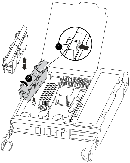
NVMEM battery lock tab
NVMEM battery
-
Locate the battery plug and squeeze the clip on the face of the battery plug to release the plug from the socket, and then unplug the battery cable from the socket.
-
Wait a few seconds, and then plug the battery back into the socket.
-
-
-
Return to step 2 of this procedure to recheck the NVMEM LED.
-
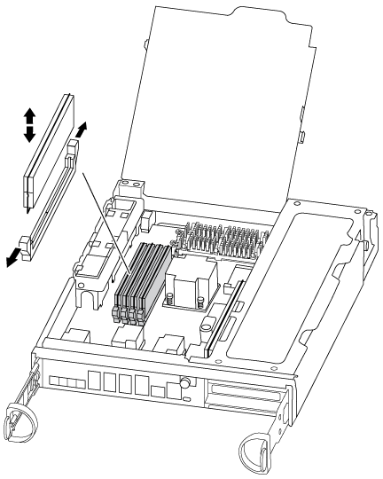
Locate the DIMMs on your controller module.
-
Note the orientation of the DIMM in the socket so that you can insert the replacement DIMM in the proper orientation.
-
Eject the DIMM from its slot by slowly pushing apart the two DIMM ejector tabs on either side of the DIMM, and then slide the DIMM out of the slot.
Carefully hold the DIMM by the edges to avoid pressure on the components on the DIMM circuit board. The number and placement of system DIMMs depends on the model of your system.
The following illustration shows the location of system DIMMs:
-
Remove the replacement DIMM from the antistatic shipping bag, hold the DIMM by the corners, and align it to the slot.
The notch among the pins on the DIMM should line up with the tab in the socket.
-
Make sure that the DIMM ejector tabs on the connector are in the open position, and then insert the DIMM squarely into the slot.
The DIMM fits tightly in the slot, but should go in easily. If not, realign the DIMM with the slot and reinsert it.
Visually inspect the DIMM to verify that it is evenly aligned and fully inserted into the slot. -
Push carefully, but firmly, on the top edge of the DIMM until the ejector tabs snap into place over the notches at the ends of the DIMM.
-
Locate the NVMEM battery plug socket, and then squeeze the clip on the face of the battery cable plug to insert it into the socket.
Make sure that the plug locks down onto the controller module.
-
Close the controller module cover.
Step 4: Reinstall the controller
After you replace a component within the controller module, you must reinstall the controller module in the system chassis.
-
If you are not already grounded, properly ground yourself.
-
Align the end of the controller module with the opening in the chassis, and then gently push the controller module halfway into the system.
Do not completely insert the controller module in the chassis until instructed to do so. -
Recable the system, as needed.
If you removed the media converters (QSFPs or SFPs), remember to reinstall them if you are using fiber optic cables.
-
Complete the reinstallation of the controller module:
The controller module begins to boot as soon as it is fully seated in the chassis.
-
With the cam handle in the open position, firmly push the controller module in until it meets the midplane and is fully seated, and then close the cam handle to the locked position.
Do not use excessive force when sliding the controller module into the chassis to avoid damaging the connectors. -
Tighten the thumbscrew on the cam handle on back of the controller module.
-
If you have not already done so, reinstall the cable management device.
-
Bind the cables to the cable management device with the hook and loop strap.
-
Step 5: (Two-node MetroCluster only): Switch back aggregates
This task only applies to two-node MetroCluster configurations.
-
Verify that all nodes are in the
enabledstate:metrocluster node showcluster_B::> metrocluster node show DR Configuration DR Group Cluster Node State Mirroring Mode ----- ------- -------------- -------------- --------- -------------------- 1 cluster_A controller_A_1 configured enabled heal roots completed cluster_B controller_B_1 configured enabled waiting for switchback recovery 2 entries were displayed. -
Verify that resynchronization is complete on all SVMs:
metrocluster vserver show -
Verify that any automatic LIF migrations being performed by the healing operations were completed successfully:
metrocluster check lif show -
Perform the switchback by using the
metrocluster switchbackcommand from any node in the surviving cluster. -
Verify that the switchback operation has completed:
metrocluster showThe switchback operation is still running when a cluster is in the
waiting-for-switchbackstate:cluster_B::> metrocluster show Cluster Configuration State Mode -------------------- ------------------- --------- Local: cluster_B configured switchover Remote: cluster_A configured waiting-for-switchback
The switchback operation is complete when the clusters are in the
normalstate.:cluster_B::> metrocluster show Cluster Configuration State Mode -------------------- ------------------- --------- Local: cluster_B configured normal Remote: cluster_A configured normal
If a switchback is taking a long time to finish, you can check on the status of in-progress baselines by using the
metrocluster config-replication resync-status showcommand. -
Reestablish any SnapMirror or SnapVault configurations.
Step 6: Return the failed part to NetApp
Return the failed part to NetApp, as described in the RMA instructions shipped with the kit. See the Part Return and Replacements page for further information.